Building a custom PC or setting up a home server is an exciting weekend project, but it is not without its technical hurdles. If your newly assembled rig refuses to boot, the culprit is often the power supply unit (PSU). Skipping proper testing can lead to catastrophic failures. If a faulty PSU surges or has unstable voltage rails, it can instantly fry your expensive motherboard, processor, and RAM. Learning how to test power supply on barebones build configurations before you finalize cable management and mount your components is a crucial skill that saves time, money, and frustration.
A barebones build typically includes the chassis, power supply, and motherboard, leaving you to install the CPU, memory, and storage. Because these systems are partially assembled, isolating a power issue requires a methodical approach. Whether you are working with a massive enterprise rackmount chassis or a compact, budget-friendly open-frame rig, verifying that your power supply delivers clean, stable power is the absolute first step toward a successful deployment.
As an Amazon Associate we earn from qualifying purchases at no extra cost to you.

Our Top Picks

What You Need
Before you begin testing, gather the necessary tools. Working with electrical components requires safety precautions and the right diagnostic gear to prevent static discharge or short circuits.
| Item | Why | Optional? |
|---|---|---|
| Barebones Chassis & PSU | The core hardware platform you are testing, ranging from standard ATX units to redundant server power supplies. | No |
| Digital Multimeter or PSU Tester | Measures the exact voltage output of the 3.3V, 5V, and 12V rails to ensure they are within safe operating tolerances. | Highly Recommended |
| Metal Paperclip or ATX Jump Starter | Used to bridge the green (PS_ON) and black (GND) pins on the 24-pin connector to trick the PSU into turning on. | No (unless using a dedicated tester) |
| Anti-Static Wrist Strap | Grounds your body to prevent electrostatic discharge (ESD) from damaging sensitive motherboard circuitry. | Yes |
| Safety Glasses | Protects your eyes in the rare event of a capacitor failure or electrical spark during initial power-on. | Yes |
Step-by-Step
Testing a power supply on a barebones build can be done using two primary methods: the paperclip test (to verify basic functionality) and the multimeter test (to verify voltage health). Follow these steps carefully to isolate and diagnose your power supply.
Step 1: Isolate the Power Supply (Time: 5 Minutes)
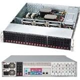
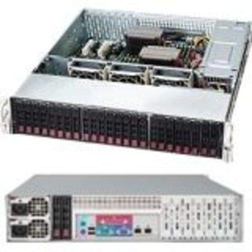
Before touching any internal cables, ensure the power supply is completely disconnected from the wall outlet. Unplug all internal power cables connected to the motherboard, graphics card, storage drives, and fans. If you are using a closed server chassis, such as the Supermicro CSE-216BAC-R920LPB 2U rackmount case ($1999.99) with its dual 920W redundant power supplies, you may need to slide the PSU modules slightly out of their bays to disconnect them from the internal distribution board. If you are using an open-air test bench, like the DIY ITX MATX ATX Computer Open Air Case ($75.6), simply unplug the 24-pin ATX power cable and the 8-pin CPU power cable from the motherboard.
Step 2: Perform the Paperclip Test (Time: 10 Minutes)
To turn on a power supply without a motherboard, you must bypass the system’s power switch. Locate the main 24-pin power connector. Look for the single green wire (Pin 16, PS_ON) and any adjacent black wire (Pin 15 or 17, Ground). Bend a metal paperclip into a U-shape, or plug in a dedicated ATX bridging tool. Insert one end of the paperclip into the green pin socket and the other end into a neighboring black pin socket. Once the bridge is secure, plug the power supply back into the wall outlet and flip the physical I/O switch on the back of the PSU to the “On” position. If the power supply fan begins to spin, the unit is receiving power and successfully initiating its internal startup sequence.
Step 3: Measure Voltages with a Multimeter (Time: 15 Minutes)
A spinning fan proves the PSU turns on, but it does not guarantee the power output is safe for your components. Turn on your digital multimeter and set it to measure DC voltage (typically indicated by a straight line over a letter V). Keep the paperclip bridge in place. Insert the black probe of your multimeter into any black (Ground) wire terminal on the 24-pin connector. Use the red probe to test the colored wires on the connector:
- Yellow Wires (12V Rail): Should read between 11.4V and 12.6V. This rail powers your CPU and GPU.
- Red Wires (5V Rail): Should read between 4.75V and 5.25V. This rail powers your storage drives and USB ports.
- Orange Wires (3.3V Rail): Should read between 3.14V and 3.47V. This rail powers motherboard logic and system memory.
If any of these readings fall outside these standard 5% tolerances, the power supply is defective and should not be connected to your motherboard.
Step 4: Test Under Minimal Barebones Load (Time: 15 Minutes)
Once the individual rails check out, turn off the PSU, remove the paperclip, and connect the 24-pin ATX and 8-pin CPU power cables back into your barebones motherboard. Keep the system minimal: install only one stick of RAM and the CPU (with cooler). Connect the power supply to the wall and use a flathead screwdriver to briefly bridge the “Power SW” pins on the front panel header of the motherboard. Observe if the motherboard diagnostic LEDs light up, if the CPU fan spins consistently, and if the system remains powered on without rebooting loop cycles.
Mistakes to Avoid
- Testing on Conductive Surfaces: Never test a barebones build or an exposed PSU on a metal table, foil, or static-generating carpet. Always use a wooden desk, a non-conductive silicone mat, or an open-frame test bench chassis.
- Bridging the Wrong Pins: Inserting a paperclip into the wrong pins (such as bridging a 12V yellow wire to a ground wire) can cause a dead short, instantly killing the PSU or causing a minor electrical pop. Double-check your 24-pin layout before turning the unit on.
- Ignoring Strange Noises or Smells: A high-pitched whining sound (known as coil whine) can be normal under load, but a clicking, buzzing, or sizzling sound is a sign of failing capacitors. If you smell ozone or burning plastic, immediately cut the power.
- Forgetting the Minimum Load Requirement: Some modern, high-efficiency power supplies will not turn on or spin their fans unless they detect a minimum electrical load. If your paperclip test fails on a high-end unit, try connecting a single case fan directly to a Molex or SATA power connector to draw a small amount of current.
How Often
You do not need to test your power supply on a weekly basis, but diagnostic checks should be integrated into your regular system maintenance routine. As we look ahead to 2026, home offices and high-performance home labs run continuously, meaning power supplies accumulate wear and tear. You should test your PSU under the following circumstances:
- During Initial Unboxing: Always test a new barebones kit or replacement power supply before mounting it permanently in the chassis.
- When Troubleshooting Boot Failures: If your PC suddenly experiences blue screens, spontaneous reboots under load, or refuses to post, the PSU should be your first point of analysis.
- Every 2 to 3 Years: For mission-critical home servers or network-attached storage (NAS) devices that run 24/7, perform a quick physical inspection and multimeter check during scheduled dust-cleaning sessions to catch voltage drift before it causes data corruption.
When to Call a Pro or Replace
Knowing when to troubleshoot and when to cut your losses is essential. If your multimeter readings show voltage fluctuations exceeding the standard 5% threshold (for example, a 12V rail dropping to 11.2V or spiking to 13.0V), the PSU is unstable. Do not attempt to open the power supply casing to repair internal components like capacitors or transformers. Power supplies contain large capacitors that can hold a lethal electrical charge for days, even when completely unplugged from the wall.
If you are working with an expensive enterprise barebones unit, such as a 2U rackmount chassis with integrated power distribution boards, diagnosing a multi-rail failure can get incredibly complex. In these cases, it is best to contact the manufacturer for a warranty replacement or consult a certified enterprise hardware technician. For budget systems, replacing a faulty, standard ATX power supply with a new, name-brand unit rated with an 80-Plus efficiency certification is much more cost-effective than attempting a professional repair.
FAQ
Can I test a power supply if it has eco-mode or zero-RPM fan features?
Yes. Many modern, high-efficiency power supplies feature a “Zero-RPM” mode where the fan does not spin under light loads to reduce noise. When performing the paperclip test on these units, the fan may spin for a brief second when flipped on and then stop. This is normal behavior. To verify the unit is active, you must use a multimeter to check the voltage outputs on the 24-pin connector.
What is the difference between testing a standard ATX PSU and a server PSU?
Standard ATX power supplies use a standardized 24-pin cable structure, making them easy to jump with a paperclip on an open-frame test bench. Server power supplies, such as the redundant hot-swap modules found in enterprise chassis, use proprietary gold-finger connection pads instead of standard cables. Testing these requires specialized distribution boards or chassis-specific diagnostic tools, as they do not have a standard 24-pin ATX connector.
Is a paperclip test completely safe for my power supply?
Yes, as long as you bridge the correct pins (the green PS_ON pin and any black Ground pin). This test merely mimics the signal the motherboard sends to the power supply when you press the power button. However, do not leave a power supply running indefinitely with just a paperclip bridge, as running a PSU with zero load for long periods can strain some older internal regulation circuits.
What does a “Power Good” signal mean?
The “Power Good” signal (usually a gray wire on Pin 8 of the 24-pin connector) is a +5V signal sent by the power supply to the motherboard once it has performed its internal self-tests and determined that all voltage rails are stable and within safe operating limits. If your multimeter reads 0V on the gray wire while the power supply is jumped, the PSU has failed its internal checks and will not allow a motherboard to boot.